

Center of Gravity and Stability
-
The CG was designed to be on the quarter chord of the wing to ensure stability
-
To prevent CG shift throughout flight, the fuel and oil tanks were placed on the CG
-
A -1° horizontal stabilizer incidence is used to overcome trim issues


Bulkheads
-
Laser Cut Aero-grade Plywood
-
1/4" deep and 1/8" thick
-
The openings will allow for access to different sections of the aircraft
Firewall
-
Mounts the engine to the fuselage
-
Two layers of 1/8" Aero-grade Plywood
-
The two layers' grain oriented perpendicular to the other
Landing Gear
-
Landing gear was designed and used for the first flight
-
Made out of stock aluminum
-
Bolted to the bottom of the fuselage
-
Easily attachable and removable

season
milestones
There have been four stages of the design and build process of this project. Each phase culminated in a milestone, either a presentation, a deliverable, or the competition. This page will serve as a guide to our design process, providing justification for design decisions made throughout the season.

aerodynamics
The Aerodynamics team was responsible for the aerodynamic configuration of the aircraft. This included the sizing of the wing and control surfaces, as well as the airfoil selection.
High Wing Design
-
More aerodynamically efficient due to easy blending into fuselage
-
Less frontal area than a mid-wing
-
Wing can double as a hatch lid for easy internal access
-
Able to run spar completely through wing without disturbing internal components
-
High ground clearance for belly landings

Conventional Tail
-
Simple construction process
-
Horizontal stabilizer is always in propeller wash to ensure control at low speeds
Wing Sizing
-
Various wingspans were tested, showing that using the maximum allowable span of 60 inches would maximize the number of flags collected in the pylon race
-
Iterating wing area and keeping the span constant showed that performance was the same from two to four square feet
-
An area of four square feet was chosen to help with a hand launch take-off
Airfoil Selection
-
Considerations for airfoil selection included performance, space for servos, and strength
-
While keeping the wing area and propeller the same, airfoils were iterated upon
-
NACA 1412, 2412, 0011, and 0012 airfoils all achieved 22 flags
-
The NACA 2412 was chosen for its camber and thickness
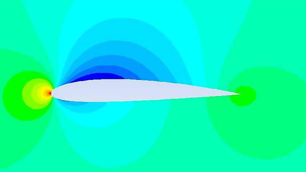
Cowling
-
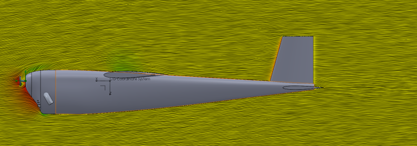
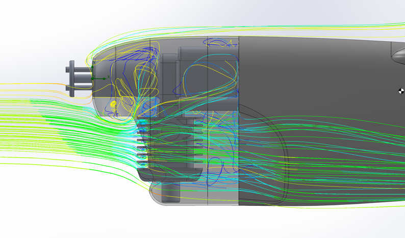
Computational fluid dynamics analyses were run on the detachable cowling to ensure that the propeller hole and the cooling hole did not cause a significant increase in drag
-
CFD was also run on the aircraft to check for flow separation around the gills that were designed as an outlet for cooling flow
-
Both analyses showed that the design choices did not significantly increase drag or cause flow separation
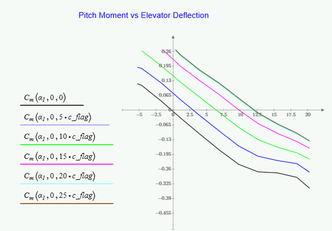
Control Surfaces
-
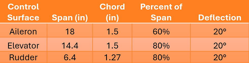
Based on initial sizing rules, all control surfaces were sized to 20% of the overall chord length
-
Larger control surfaces were desirable for aerobatic handling
-
Final sizing was done using the simulation
-
Servos were sized off of the final control surface sizes
Simulation
-
Utilized simulation to check control surface sizing and effectiveness
-
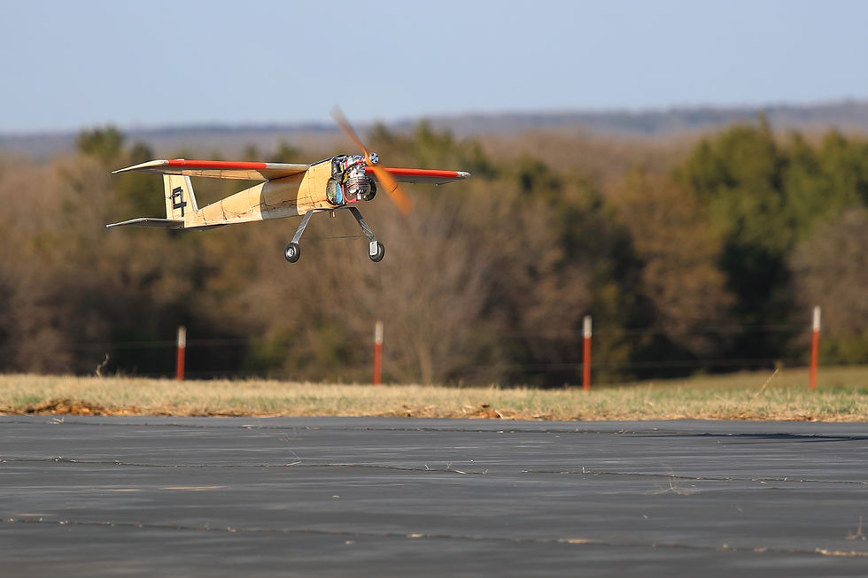
Verified hand launch option by simulating hand launch conditions
Propulsion
The Propulsion team was responsible for the engine, including testing and integration onto the airframe along with propeller choice. Additionally, the Propulsion team built and tested the smoke system.
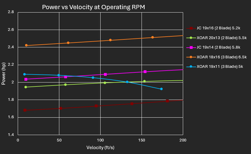
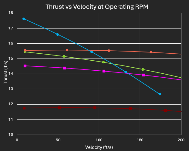
Propeller Testing
-
Two-blade and three-blade propellers were tested and compared
-
Two-blade propellers were chosen because they reached higher speeds, more fuel efficient, and were safer for a belly landing
-
A 20x13 was used to size the fuel tank for ten minutes of full throttle time; the minimum size is 8.7 oz


Custom Exhaust
-
Tested custom exhaust compared to stock DA muffler
-
Custom muffler weighed less
-
Custom has reduced frontal area
-
Testing done to ensure no performance loss
-
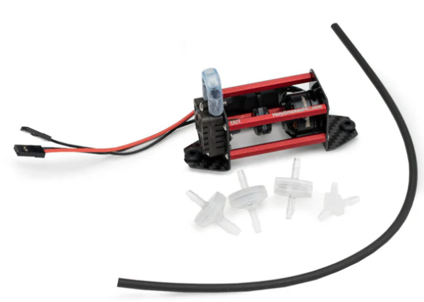
Smoke System
-
The Holy Smokes smoke pump was chosen for its low weight and ideal performance
-
Smoke oil is pumped from the smoke oil tank (right) and sprayed into the exhaust, creating smoke
-
Super Clean 13 Aviation Smoke Oil, commonly used in RC and full-scale planes, was chosen for its smoke point
-
Thirty seconds of smoke is required, minimum tank size was determined to be 1.85 fl-oz

Engine Testing
-
Engine testing was done with a XOAR 20x8 propeller to break-in the engines
-
Various smoke rates were tested to ensure the oil would reach its smoke point at a given throttle setting
-
All six engines were tuned to achieve optimal performance for chosen propellers
structures
The Structures team was responsible for material testing, mold fabrication, aircraft construction, and final assembly
Mold Lines
-
Utilized three molds
-
Left/right mold for fuselage
-
Top/bottom mold for horizontal stab and wing


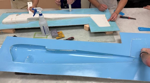
Making the Molds
-
Mold "plugs" were CNC'd out of high-density foam, primed, and sanded
-
Two layers of gel coat were spread over the plugs
-
Sharp corners were reinforced with colloidal epoxy
-
Thirteen layers of tooling fiberglass were then laid up over the gel coat and colloidal to reinforce the mold
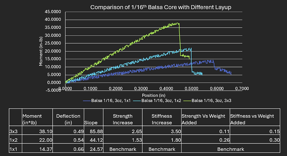
Materials Testing
-
Testing was done to determine which materials would be used.
-
Each material was weighed, then the strength and stiffness were tested.
-
A layup of one layer of 3oz fiberglass, 1/16th inch balsa core, and another layer of 3oz fiberglass was chosen


Wing Spar
-
Designed for stiffness rather than ultimate strength
-
2.5% wingtip deflection at 16 G loading
-
Analysis of the lift distribution showed that the spar needed to be 54" (90% of wing span)
-
No ribs are required for this design, torsional loads are handled by the skin
-
The spar is composed of 1/8" sitka spruce shear web with a 0.01" thick spar cap of 1" unidirectional carbon fiber
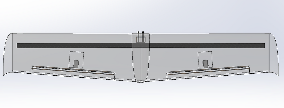

Wing Integration
-
Two 0.28" OD carbon fiber tubes are bonded into wing slide and into two 0.3" ID carbon fiber receivers that are bonded into the front bulkhead
-
The trailing edge of the wing is bolted into place with a single 10-32 machine screw
-
The screw integrates into a blind nut that is bonded into the fuselage via Sitka Spruce blocking
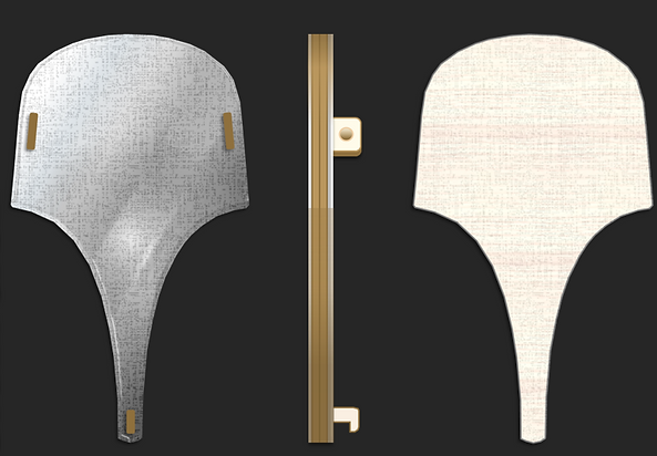
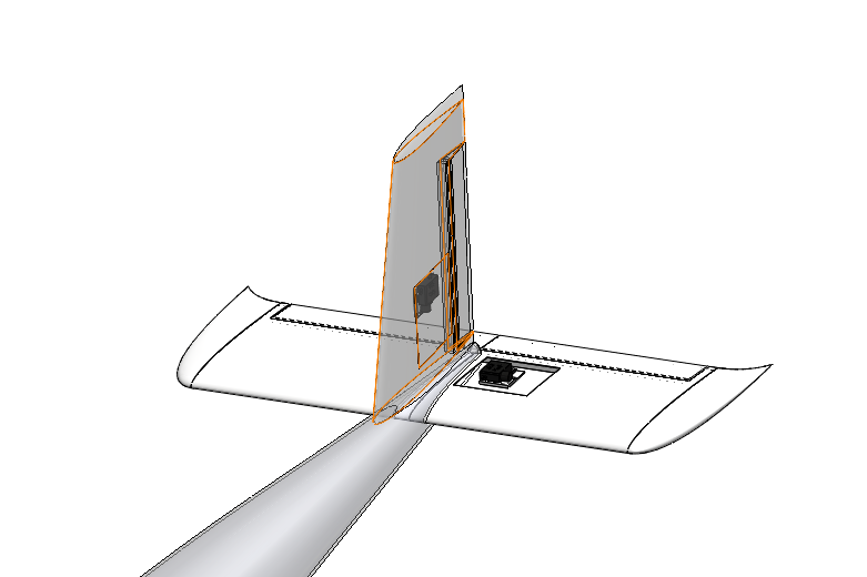
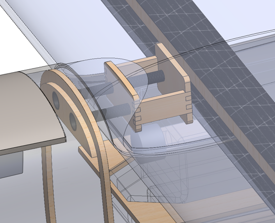
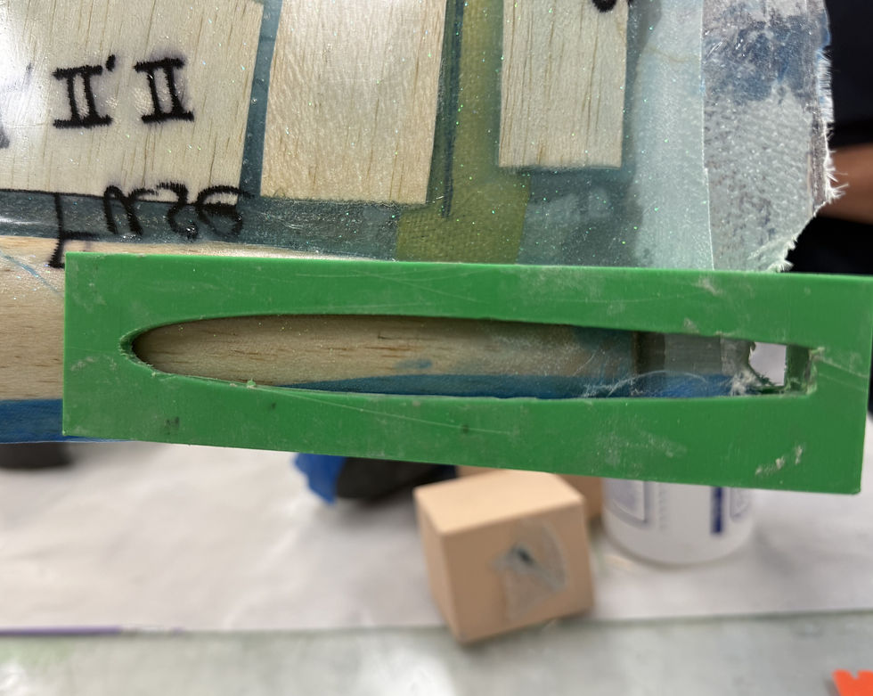
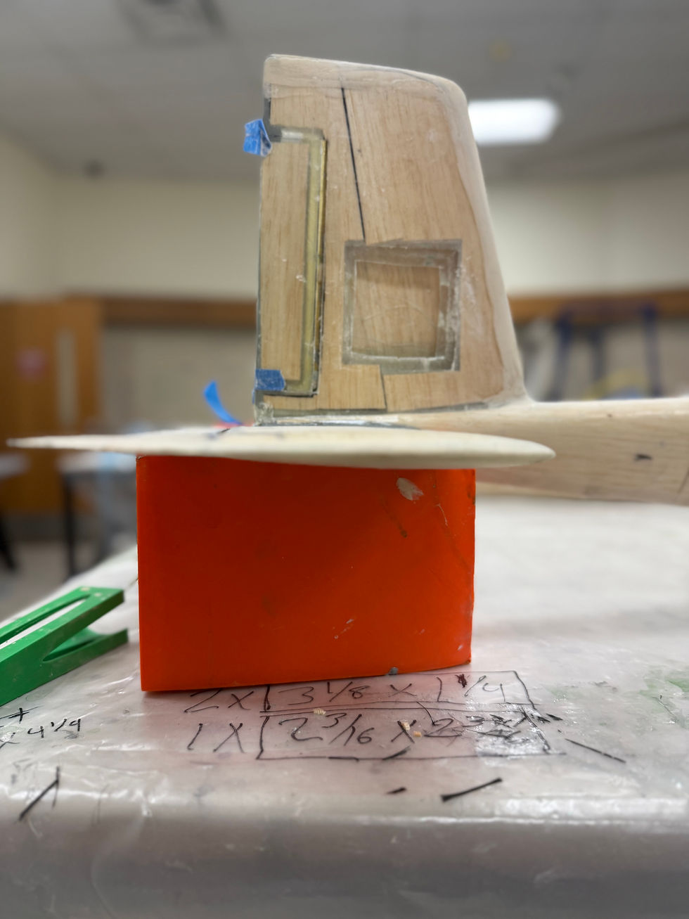
Horizontal Stabilizer Integration
-
A 3D-printed jig is used to cut the shape for the stabilizer in the fuselage
-
A second jig is used to hold the stabilizer and fuselage while epoxy is used to bond the pieces together
.jpg)
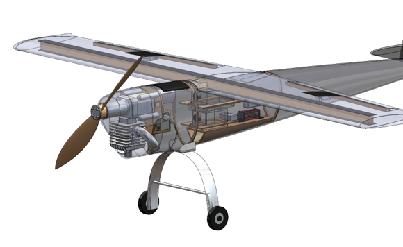
Internal Mounting
-
Laser-cut trays hold tanks in laterally and longitudinally
-
Laser-cut platform to mount receiver in perfect horizontal orientation
-
Batteries and smoke pump secured with Velcro
-
Throttle servo bracket and aileron servo bracket attached with epoxy
-
Tail servos mounted with plastic, manufactured bracket
.jpg)
.jpg)

Cowling
-
"Clam-Shell" design enables easy attachment and removal
-
Hole cut for immediate access to the carburetor needles
-
Attached to fuselage via machine screws
